 Something I’ve been wanting to do for a while: Convert a mechanical gauge to display sensor data, such as temperature or water tank levels, rather than display data on a screen. At the start of 2016 I picked up a couple of pressure gauges from an antique bazaar. Here’s the story of one gauge’s conversion.
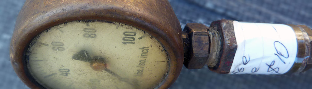
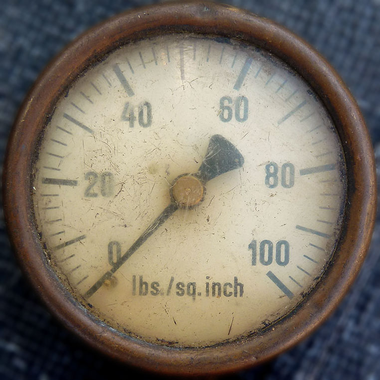
I chose this gauge because the scale ran from 0 to 100 (psi) — perfect for displaying percentage data, such as the level of a water tank or how much download quota you’ve used.
The other gauge I purchased has a kPa scale of 0 to 40, which seemed a good fit for displaying outside temperature (degrees C) in these parts. I didn’t document that modification but you can see the final result in a couple of the images further down and in the video.
My first task was to dismantle the brass gauge. The front bezel and lens came off easily by loosening two screws, but the needle was incredibly hard to budge. Even after applying heat, cold and penetrating oil, it only came off with the application of a lot of force. My main goal was to avoid bending the needle or scratching the dial. Success on both counts. 🙂


Then it was time to assess the mechanical setup inside and remove any unnecessary parts and decide where to mount a servo and how to drive the needle. This gauge was quite roomy inside so I had a lot of options for mounting the micro servo I had on hand. Being a fairly old gauge, the main mechanism was assembled with screws, making it easy to remove and reinstall throughout the process of mulling over how to connect up the mechanical parts and testing different options.
Another issue that needed resolving was that my servo had a range of only 150 degrees, but the full scale of the dial was about 270 degrees — so I had to build in a drive ratio of about 1.8:1. My usual Chinese superstore gave me many possible solutions to that problem with a low-cost bag of plastic gears.
 gear added")


With the final solution and gearing selected, I used a Dremel to cut beneath the axle. This allowed the servo drive gear to move without interfering with the driven gear and the brass casing. I made small modifications to each gear to get them to press-fit onto the servo and needle axles.
I set the final servo position by molding some polymorph plastic into the case and around the servo, then gluing the polymorph into place with 2-part epoxy glue.
During the build process I cleaned and polished all of the key parts. I also bored a larger hole where the gas used to enter the gauge and pulled the servo cable through.
Reassembly was straightforward — it simply involved screwing things back together. I reinstalled the needle (gently) after calibrating the servo’s range.

")


To test, I hooked both gauges up to an Arduino nano and a temperature sensor and wrote a program to sweep the needle across the full range and then to set the needle based on temperature.
My final step with this project is to find a suitable mount for the gauges and use a Raspberry Pi to drive them.
I’m especially pleased with the finished brass gauge and will be on the lookout for more like it to tinker with.