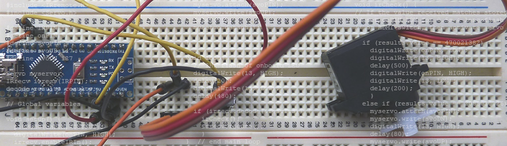
This is the outline of the Arduino code and schematics for the Remote Enhancements project.
This was a two-part project: Firstly, determine the codes coming from the TV’s remote control; Secondly, to listen for and respond to specific codes.
The set up and Arduino code for the first part is remarkably simple. Connect the IR receiver module to power, ground and a digital input pin on the Arduino. Upload the code to the Arduino (make sure the correct pin is specified in the code) and then open the serial monitor. When a button on a remote control is pressed, the associated code is displayed in the Arduino’s Serial Monitor window.


/*
IR Remote code reader
The circuit: IR module to d10
*/
#include <IRremote.h>
#define IRPIN 10
IRrecv irrecv(IRPIN); // create instance of 'irrecv' on IRPIN
decode_results results; // variable to hold incoming codes
void setup() {
irrecv.enableIRIn(); // Start the receiver
Serial.begin(9600);
}
void loop() {
// 2Hz flash of onboard LED
digitalWrite(13, HIGH);
delay(20);
digitalWrite(13, LOW);
delay(480);
if (irrecv.decode(&results)) {
irCheck();
irrecv.resume();
}
} // end main loop
void irCheck() {
Serial.println(results.value);
}
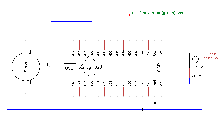
For the final project goal, digital pin d05 was connected to the PC’s power-on wire (green from the ATX power supply). When this line is connected to ground (via a digital LOW signal), the computer starts. The servo motor was mechanically attached to the HDMI switch and a servo horn was attached to act as a short lever. When the servo moves a few degrees, the button on top of the HDMI switch is pressed down. The amount of servo movement needed was determined by trial and error.
/*

IR Remote on for HTPC
v1.0 150719 - Set up IR receiver
v1.1 150722 - Add servo for HDMI switcher

  The circuit:
 * IR LED data to d10
 * Output d05, active low, to ground power-on rail
 * Servo on d09

 Remote Signals from Samsung TV control
 470021382 = STB
 2088030026 = CABLE
 4200456840 = VCR
 1625891106 = TV

*/

#include <IRremote.h>
#include <Servo.h>

#define IRPIN 10
#define onPIN 5
#define svoPIN 9
#define svoUP 147
#define svoDN 127

Servo myservo;            // create servo object to control a servo
IRrecv irrecv(IRPIN);     // create instance of 'irrecv' on IRPIN
decode_results results;   // variable to hold incoming codes

// Global variables

void setup() {
  pinMode(onPIN, OUTPUT);   // set the power-on pin for output and active LOW
  digitalWrite(onPIN, HIGH);
  irrecv.enableIRIn();      // Start the receiver
  myservo.attach(svoPIN);   // attaches the svoPIN to the servo object
  myservo.write(svoUP);
  delay(75);
  myservo.detach();

}

void loop() {
  // 2Hz flash of onboard LED
  digitalWrite(13, HIGH);
  delay(20);
  digitalWrite(13, LOW);
  delay(480);

  if (irrecv.decode(&results)) {    // New code received? See if it needs action and then restart the IR receiver
    irCheck();
    irrecv.resume();
    }
}  // end main loop

void irCheck() {
// If the value received matches stored code for PC power on,
// set onPIN LOW for 0.5s & long-flash onboard LED
// or HDMI switch, then activate servo

  if (results.value == 470021382) {         // code to turn PC on
    digitalWrite(onPIN, LOW);               // ground power on pin
    digitalWrite(13, HIGH);
    delay(500);                             // wait a moment
    digitalWrite(onPIN, HIGH);              // return power pin to HIGH state
    digitalWrite(13, LOW);
    delay(200);
    }
  else if (results.value == 2088030026) {   // code to activate HDMI switch
    myservo.attach(svoPIN);                 // attach servo interrupt first
    myservo.write(svoDN);                   // move to pressed position
    digitalWrite(13, HIGH);
    delay(80);                              // delay to give servo time to move
    myservo.write(svoUP);                   // return servo to up position
    delay(30);                              // delay to give servo time to move
    digitalWrite(13, LOW);
    myservo.detach();                       // detach servo object to stop jitter
  }

}    // end irCheck